Design of a Multi Storied Building Using ETABS CSI
• Number of Storey: G+4 including stair cover
• Building Type: Residential Building
• Building Height: 20.5m {(4 × 4) + (4.5 × 1)}
• Column → 400 × 400mm
450 × 450mm
500 × 500mm
• Beam → 350 × 400 mm
300 × 350 mm
400 × 450 mm
• Slab Thickness: 150 mm
• Staircase Thickness: 175 mm
• Wall Thickness: 250 mm
• Load → Dead Load – 2 Kn/m2 Live Load – 5 Kn/m2

STEPS
STEP 1: Open ETABS→ Select New Model

STEP 2: Select → User setting from a
modal file→ Already set data for Built in Setting with INTRO.

STEP 3: Spacing Of Grids in X
direction-7m and in Y direction=7m.

STEP 4: Right click anywhere between
the grids. A popup will appear select add or modify grids.

STEP 5: Select modify/show storey data.

We can alter the height and storey
data here. We will also be able to change the number of storeys and other data.

STEP 6: Now, go to DEFINE select
material properties.

STEP 7: Then go to ADDNEW MATERIAL.
Add concrete and rebar using the standard is code. Here specify the data for
the required concrete.

STEP 8: Similarly, you can insert your
rebar data as per IS CODE.


Now, the material selection has
been completed.

STEP 9: Now go to DEFINE→ select
SECTION PROPERTIES → select CONCRETE RECTANGULAR SECTION.
STEP 10: Now specify the concrete
details required for your column.

STEP 11: Similarly specify the data as
per IS CODE → go to modify/show modifier.

STEP 12: Now, go to show modifier and
specify data as per IS CODE

STEP 13: Now, change other data here as
per IS CODE.

STEP 14: On this popup, we are
specifying a beam. So, we select beam from this table and fill the rest of data
as shown.

STEP 15: Similarly, here we fill the
data as per the IS CODE recommendations for beam.

STEP 16: Now go to DEFINE→ select SECTION PROPERTIES → select Wall Sections.

Define the wall data as per
requirements.

STEP 17: Now go
to DEFINE→ select SECTION PROPERTIES → select Wall Sections and define
staircase details.

Now, all the details and materials
has been specified along with beams, columns, slabs and stairs. So, now one can
start placing beams and columns on the grids.
STEP 18: Now, click on the shortcut
button for QUICK DRAW COLUMNS and drag and draw the columns.

STEP 19: Then similarly, select the
shortcut for QUICKDRAW BEAMS and drag and draw the beam on the plan grid.

STEP 20: Follow the same procedure for
all storeys.

STEP 21: Add slabs to the building using the shortcut
buttons for quickdraw slab.
STEP 22: Draw walls to the building
using the quick draw walls button from the left shortcut menu.
STEP 23: Put openings on either side of
the plan for staircases.
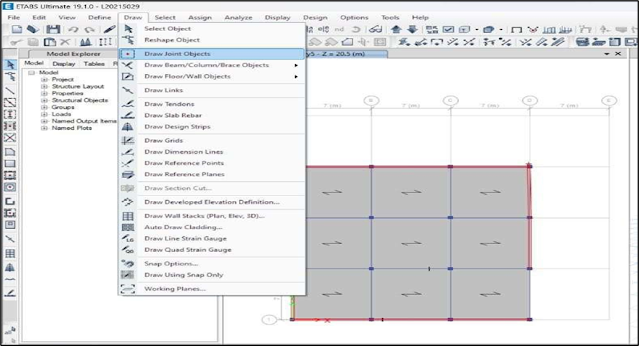
STEP 24: Now go to draw → select draw joint objects and
define joint objects.
After the opening is
provided, the plan will look like this:

STEP 25: Select the desired area for
staircase and select → SHOW SELECTED OBJECTS ONLY.

STEP 26: Then go to DRAW select → DRAW
USING SNAP.

STEP 27: Then draw a beam at the midpoint of column for landing.

STEP 28: Draw slabs at the landing
spots.

STEP 29: Then draw stairs using tools
from the left shortcut menu.
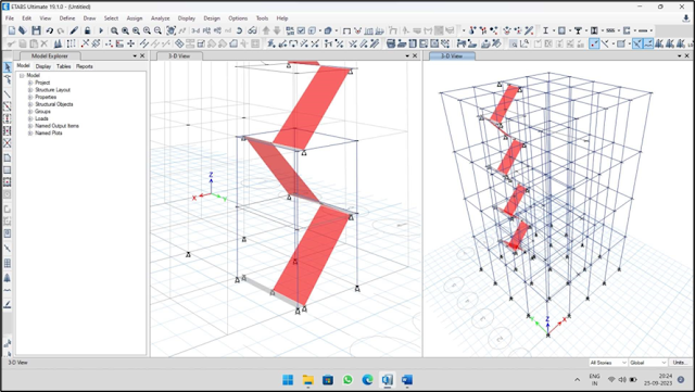
After the staircase is completed,
the building looks like this:

STEP 30: Now go to Assign → Shell Loads
→ Uniform→ Dead=2 → Live =5 → Click Ok.

STEP 31: Now click on Analyse /F5 to run Analysis→ Run Analysis→ Save File→ Output Result Shown.

STEP 32: Click on Display Frame→ For
showing BM, SF and Stress Diagrams. Select Moment 33→Show Values→ Click Apply→
Shows the Bending Moment Diagram.

STEP 33: Click on Display Shell
Stresses→ Select M22→Click on Apply→ It Shows the stress.

STEP 34: Click Display Shell Stresses→ Select M Max→ Click on Apply→ OK → It shows the Maximum Bending Moment.

Comments
Post a Comment